Cavity mapping
Virtual screening is very rarely conducted against entire macromolecules. The usual practice is to dock small molecules in a much more confined region of interest. RxDock makes a clear distinction between the region the ligand is allowed to explore (known here as the docking site), and the receptor atoms that need to be included in order to calculate the score correctly. The former is controlled by the cavity mapping algorithm, whilst the latter is scoring function dependent as it depends on the distance range of each component term (for example, vdW range >> polar range). For this reason, it is usual practice with RxDock to prepare intact receptor files (rather than truncated spheres around the region of interest), and to allow each scoring function term to isolate the relevant receptor atoms within range of the docking site.
RxDock provides two methods for defining the docking site:
Two sphere method
Reference ligand method
The two methods are explained and illustrated below using PDB structure 2hr1.
Note
All the keywords found in capital letters in following cavity mapping methods
explanation (e.g. RADIUS), make reference to the parameters defined in
prm RxDock configuration file. For more information, go to Cavity
mapping subsection in System definition file
section.
Two sphere method
The two sphere method aims to find cavities that are accessible to a small sphere (of typical atomic or solvent radius) but are inaccessible to a larger sphere. The larger sphere probe will eliminate flat and convex regions of the receptor surface, and also shallow cavities. The regions that remain and are accessible to the small sphere are likely to be the nice well defined cavities of interest for drug design purposes.
The method is explained and illustrated in Figure 3, Figure 4, Figure 5, Figure 6, Figure 7, Figure 8, and Figure 9.
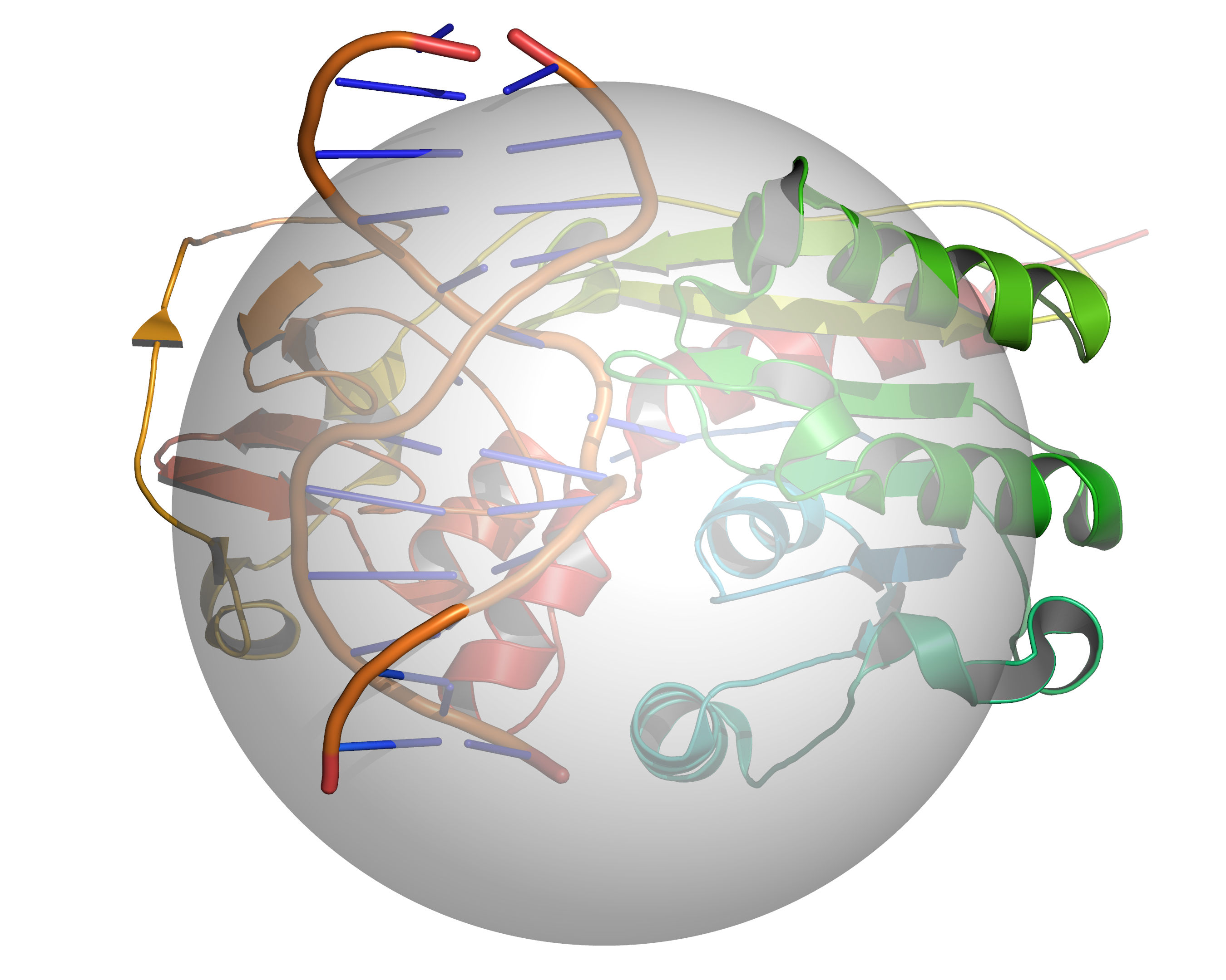
Fig. 3 A grid is placed over the cavity mapping region, encompassing a sphere of
radius = RADIUS, center = CENTER. Cavity mapping is restricted to
this sphere. All cavities located will be wholly within this sphere. Any
cavity that would otherwise protrude beyond the cavity mapping sphere will be
truncated at the periphery of the sphere.
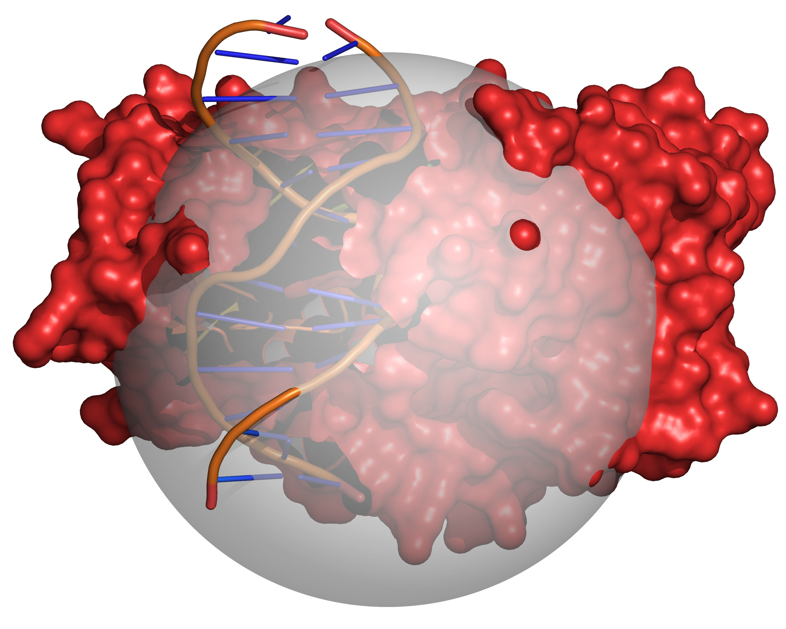
Fig. 4 Grid points within the volume occupied by the receptor are excluded (coloured
red). The radii of the receptor atoms are increased temporarily by
VOL_INCR in this step.
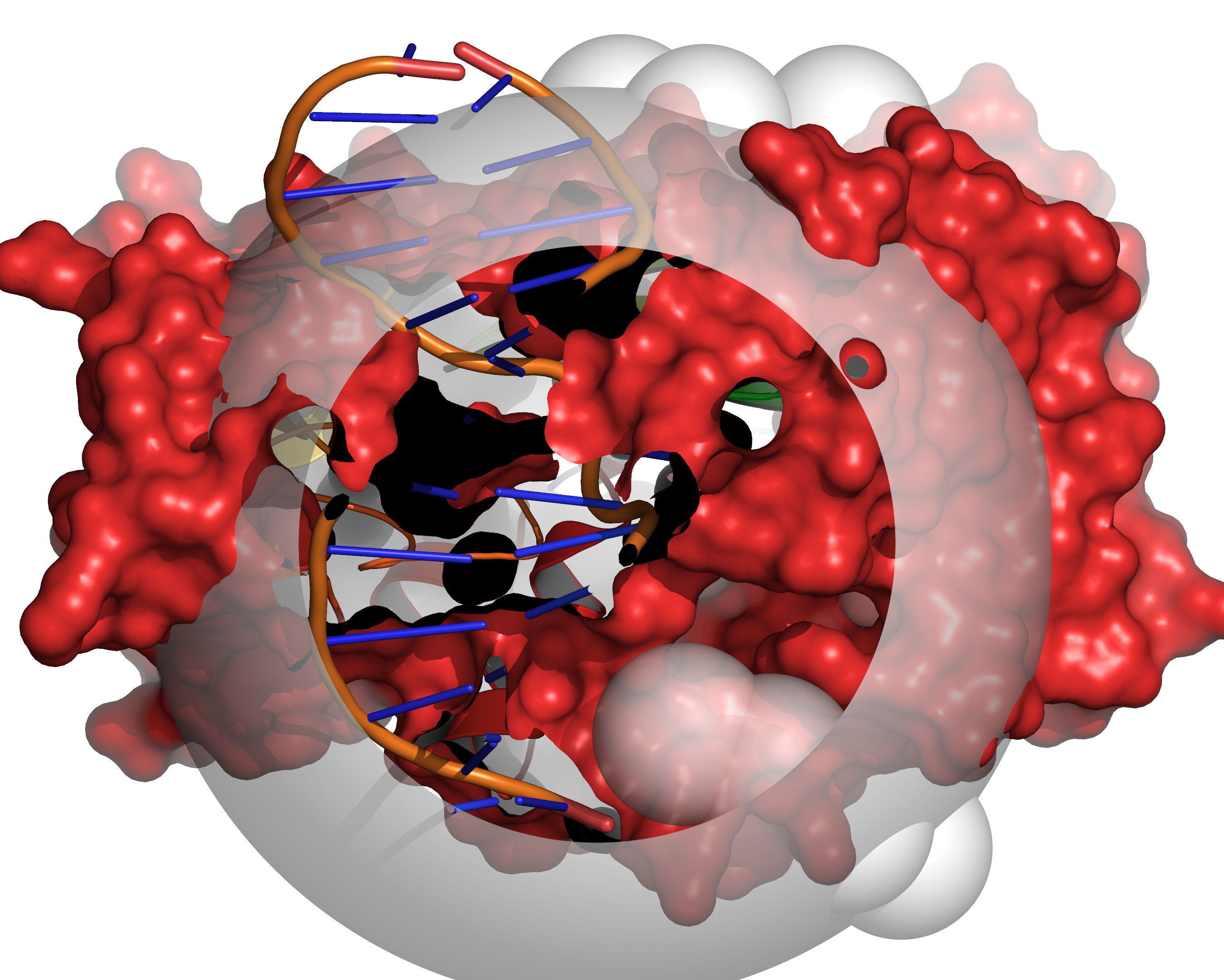
Fig. 5 Probes of radii LARGE_SPHERE are placed on each remaining unallocated
grid point and checked for clashes with receptor excluded volume. To
eliminate edge effects, the grid is extended beyond the cavity mapping region
by the diameter of the large sphere (for this step only). This allows the
large probe to be placed on grid points outside of the cavity mapping region,
yet partially protrude into the cavity mapping region.
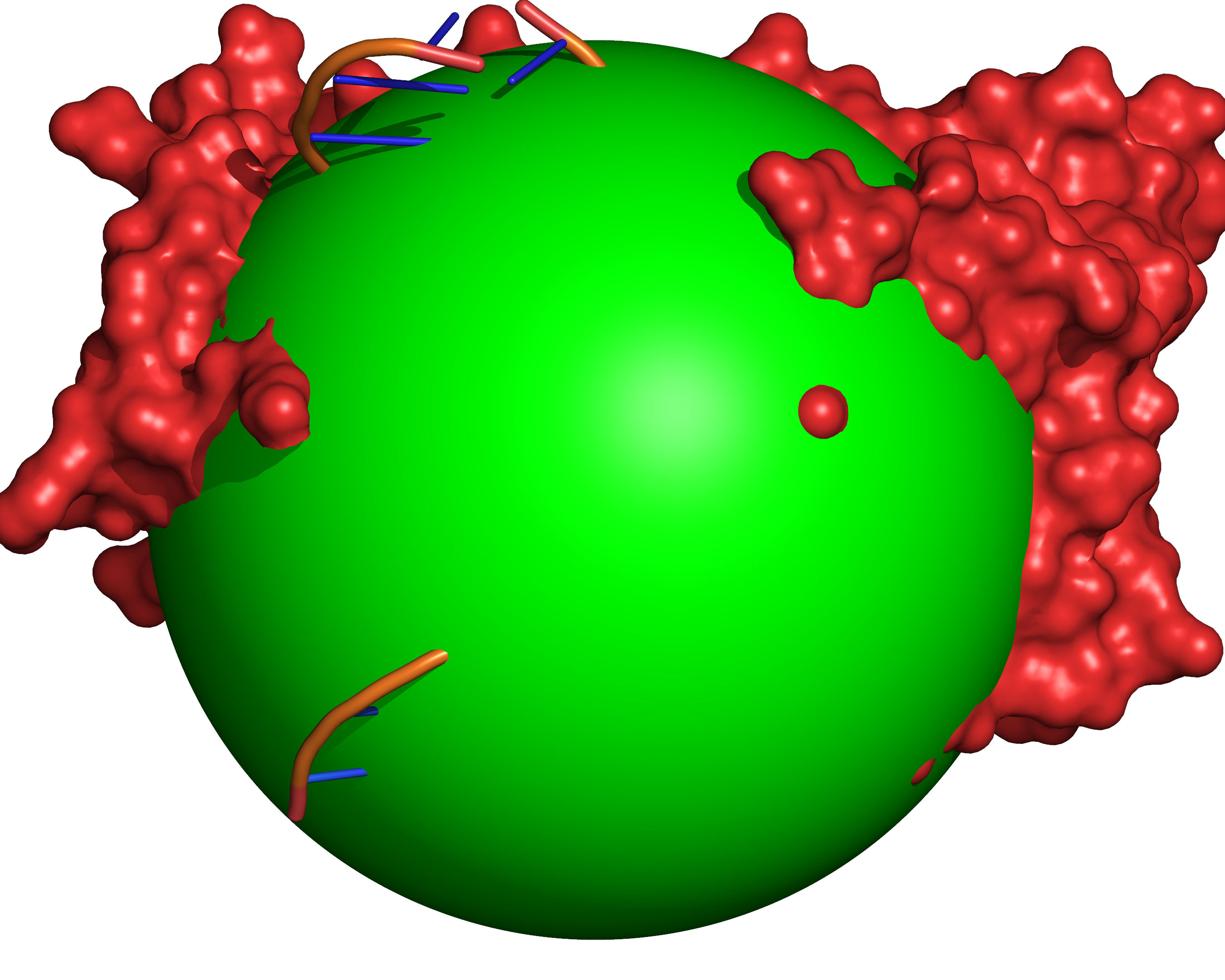
Fig. 6 All grid points within the cavity mapping region that are accessible to the large probe are excluded (coloured green).
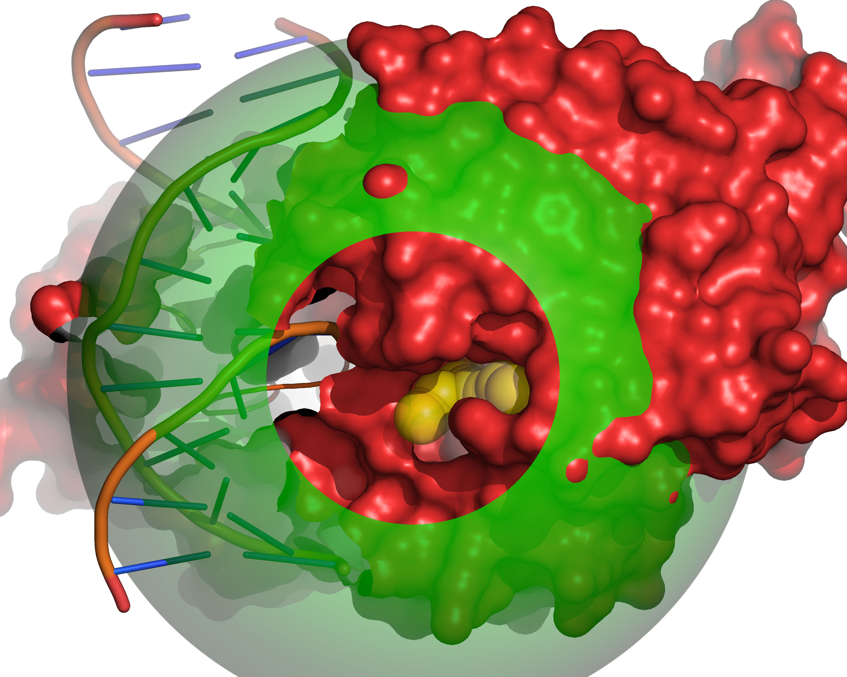
Fig. 7 Probes of radii SMALL_SPHERE are placed on each remaining grid point and
checked for clashes with receptor excluded volume (red) or large probe
excluded volume (green).
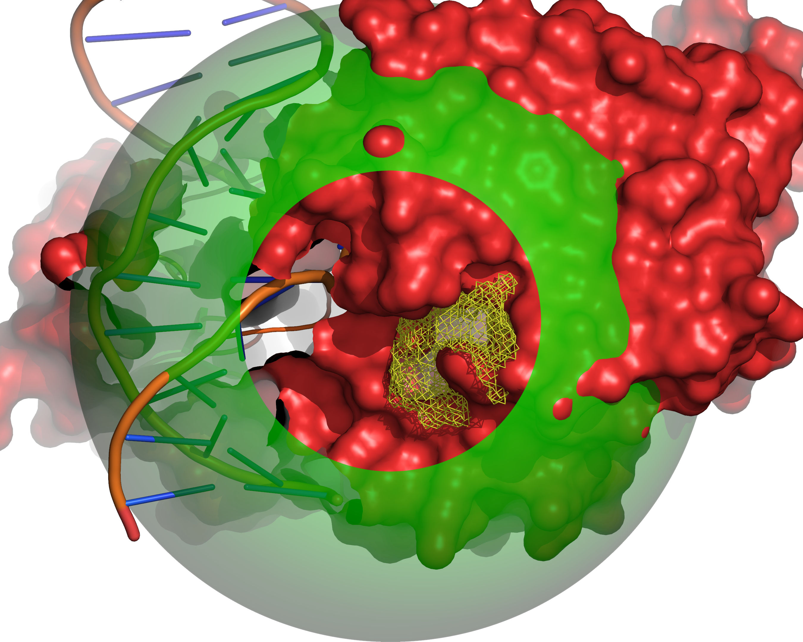
Fig. 8 All grid points that are accessible to the small probe are selected (yellow).
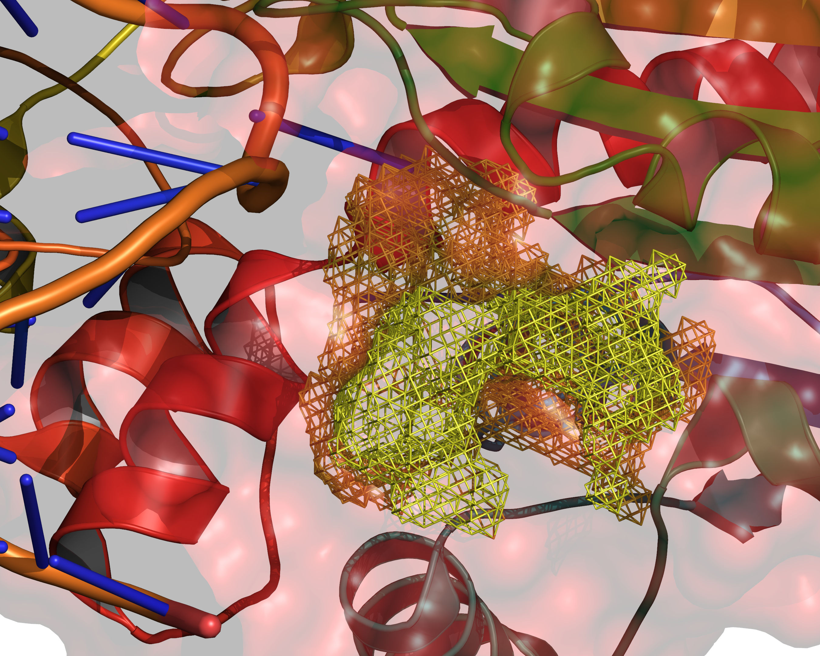
Fig. 9 The final selection of cavity grid points is divided into distinct cavities
(contiguous regions). In this example only one distinct cavity is found.
User-defined filters of MIN_VOLUME and MAX_CAVITIES are applied at
this stage to select a subset of cavities if required. Note that the filters
will accept or reject intact cavities only.
Reference ligand method
The reference ligand method provides a much easier option to define a docking volume of a given size around the binding mode of a known ligand, and is particularly appropriate for large scale automated validation experiments.
The method is explained and illustrated in Figure 10, Figure 11, Figure 12, and Figure 13.
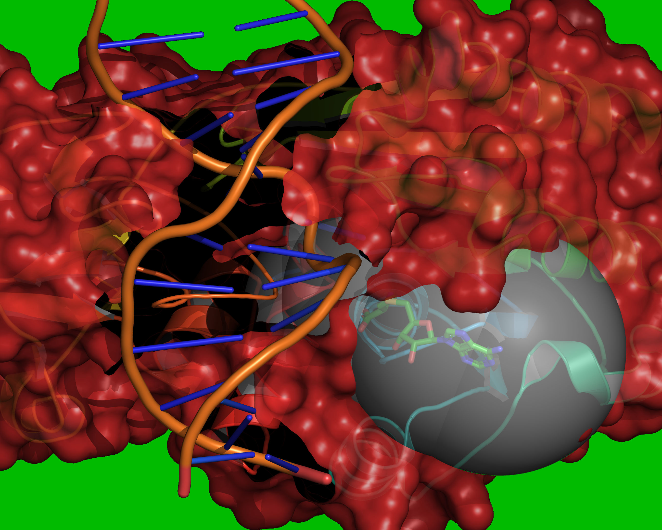
Fig. 10 Reference coordinates are read from REF_MOL. A grid is placed over the
cavity mapping region, encompassing overlapping spheres of radius =
RADIUS, centered on each atom in REF_MOL. Grid points outside of the
overlapping spheres are excluded (coloured green). Grid points within the
volume occupied by the receptor are excluded (coloured red). The vdW radii of
the receptor atoms are increased by VOL_INCR in this step.
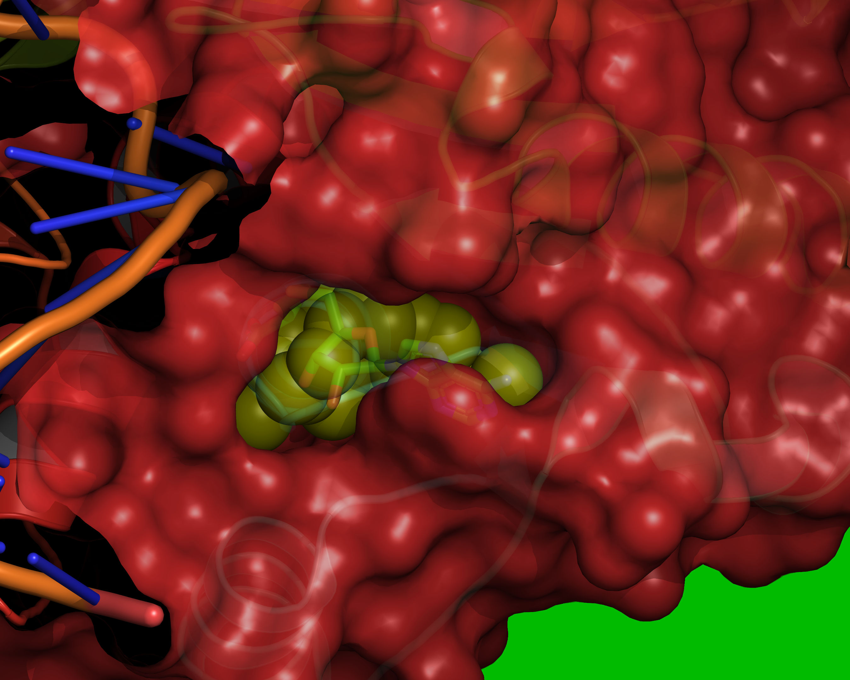
Fig. 11 Probes of radii SMALL_SPHERE are placed on each remaining grid point and
checked for clashes with red or green regions.
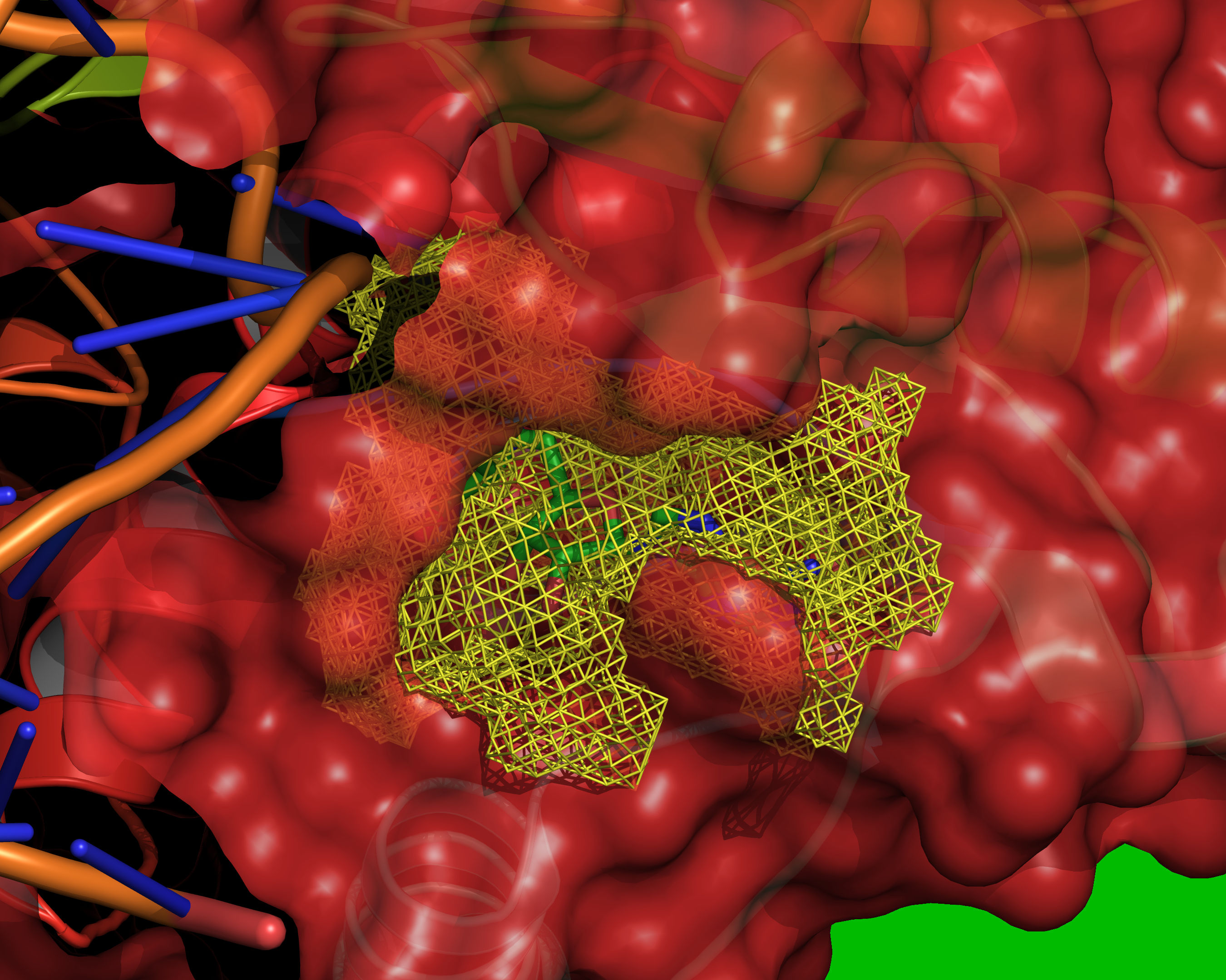
Fig. 12 All grid points that are accessible to the small probe are selected (yellow).
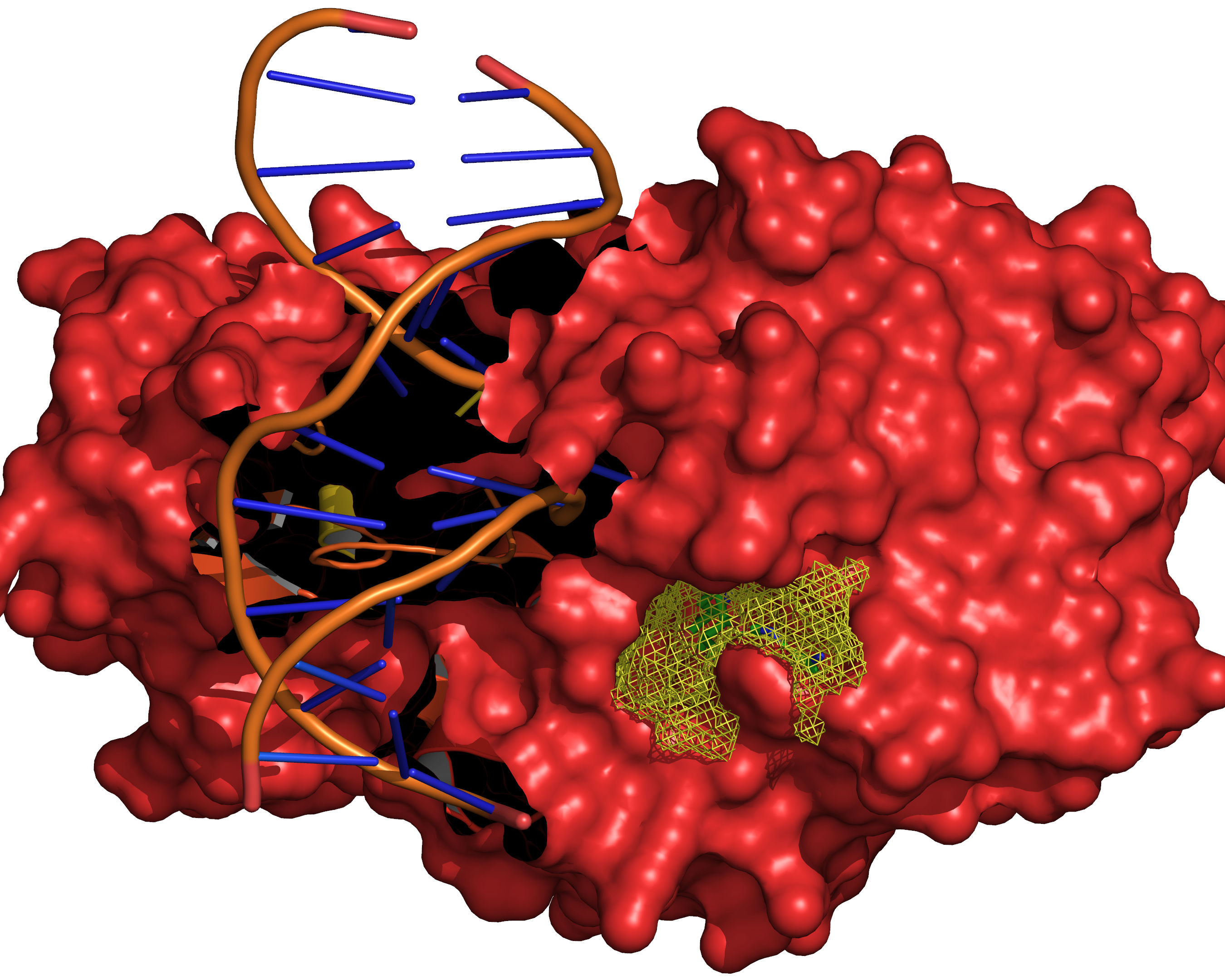
Fig. 13 The final selection of cavity grid points is divided into distinct cavities
(contiguous regions). In this example only one distinct cavity is found.
User-defined filters of MIN_VOLUME and MAX_CAVITIES are applied at
this stage to select a subset of cavities if required. Note that the filters
will accept or reject intact cavities only.